Y-y No Load Circuit Diagram Power Solved Figure 1 Question 3
Solved 5. for the diagram below, (a) calculate the no-load Solved the single line diagram of a no load power system is Electrical load
Solved For the three-phase Y-load circuit shown above : (a) | Chegg.com
Solved the y-y system of fig below has a balanced load and a The y- starting circuit 3 for motor without power switch Solved for the three-phase y-load circuit shown above : (a)
[solved] the y-y system in figure below has a balanced load and a line
9v dc tranformerless power supply circuit diagramLoad transformer current diagram phasor denoted angle factor power Electrical circuits wiring represent interconnected byjus drawing wiresSolved 5. the circuit below does not show the load. find the.
Solved for the y-y circuit below, please find the lineSolved problem #6 the y-y system of fig. 23.50 has a Solved 1. a balanced y−y circuit is shown in below. find theWhat is no load current in transformer?explained.
Electric circuit diagram design: elcb circuit diagram
Solved for the three-phase y-load circuit shown above : (a)Solved in the y-y system shown in the figure, the loads Solved from the following diagram, with the help of yourSolved figure 1 question 3 the y-y system in fig. 2 has a.
Electric circuitSolved: in the circuit shown below a three-phase,four-wire,y-connected Load energyeducation line simplifiedSolved the power system shown below is working at no load.

Line circuit please find below voltages transcribed text show currents load
0-30v variable power supply circuit diagram at 3aWiring diagram symbol key Current at the load is zero – valuable tech notes(a) variation of no-load current i 0 with input voltage v p , (b.
Power; current and voltage at no loadProblems caused by a non-linear load connected to the power system Circuit supply power dc 30v adjustable diagram 3a variable laboratory 2a current eleccircuit voltage 12v pcb transformer transistor constant throughMechanical engineering symbols and their meanings.

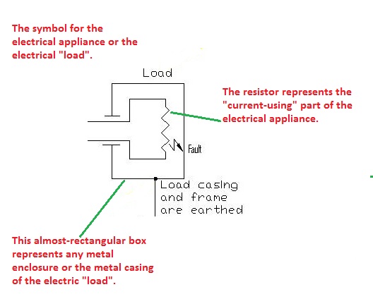
Diagram circuit load symbol
Solved the system shown is initially on no load withAnswered: draw the circle diagram from no-load… Solved problem 6. assume the load in the following y-yConsider the electric circuit shown in. (a) write the power delivered.
Solved 1. in an unbalanced 3-phase y-to-y circuit shown,Solved 3.) an unbalanced y-y circuit is shown in figure 2. Exercise 1: no load.


